Latest
News
return to Home page
19th March 2007
-
Bolter progress
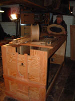
The bolter has now been installed in the mill
after some manoeuvring involving enlargement of the hole! The hopper frame has
been built; this was very difficult due to the angles involved and the cramped
access. In the end though it is a good fit, but we have not installed it yet as
we are currently working on the rear bearing mount frame, which would be
impossible with the hopper in position. As can be seen in the photo, the shaft
has been temporarily installed; this will enable us to position the rear
bearing. Part of the rear bearing frame is an original piece which will be the
only original part; it was luckily still in situ even though the remainder of
the bolter had disappeared.
|
|
|
|

|
|
|
|
The bolter in position at the rear of the stone floor on March 11th |
|
|
|
|
|
|
|
|
|
|

|
|
|
|
Compare this to the photo below........... |
|
|
|
|
|
|
|
|
23rd July 2006
-
Bolter progress
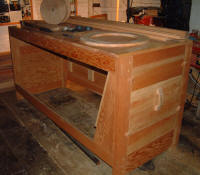
We have almost finished manufacture of the main
feed hopper, which just needs the entry hatch cut out. The hopper has been moved
temporarily to the spout floor as we are struggling with room in the roundhouse.
The main bolter shaft is now nearing completion so
we have turned our attention to the fitting of the bolter in the rear of the
stone floor. The old floor, which was actually only installed in the 1960's has
been removed and a start made on working out how the bolter can safely be bolted
within the floor void.
|
|
|
|

|
|
|
|
Looking up through the floor void where the bolter will be mounted. . |
|
The underside of the bins and bin floor is in view with the roof rafters beyond; the open doorway to the buck is at the bottom of the photo. |
|
|
|
|
|
|
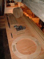
. This is made from Douglas Fir and is fully mitred at the corners.")
|
|
|
|
The feed hopper (inverted). This is made from Douglas Fir and is fully mitred at the corners. |
|
|
|
|
|
|
|
|
|

|
|
|
|
Checking the floor void for squareness is Gordon Hinton, one of our volunteers. |
|
|
|
|
|
|
|
|
26th
February 2006
-
Bolter progress
back to top of page
The bolter is basically a rotating sieve for
grading the flour and is the last part of the restoration of the windmill.
Although the original bolter was missing, by some good fortune we still have the
remains of the central oak shaft plus a photograph taken in 1955 of the remains
in situ, although I have to say that there was not much there! I knew of a
bolter in Keston windmill near Bromley and a visit confirmed that it was almost
identical in size and best of all the shaft was exactly the same size. So after
several visits to measure the Keston bolter in detail the work began in November
2003 and is continuing after the production so far of 55 working drawings.
|
|

|
|
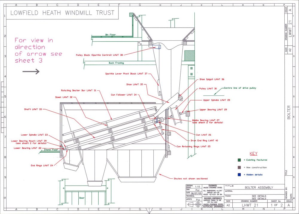
The general assembly drawing (AutoCAD)
|
|
|
|
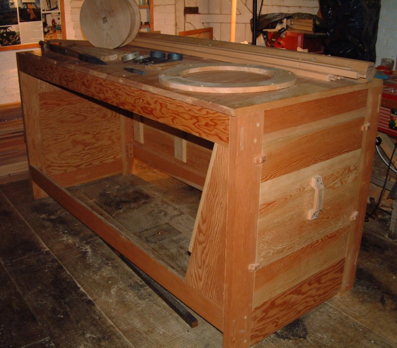
The face on the left will actually be against the rear wall of the mill once installed and so will not be seen.
The end cover can be seen on the right for access to the bolting cloth and lower bearing. All of the frame and covers are made of Douglas Fir. |
|
|
|
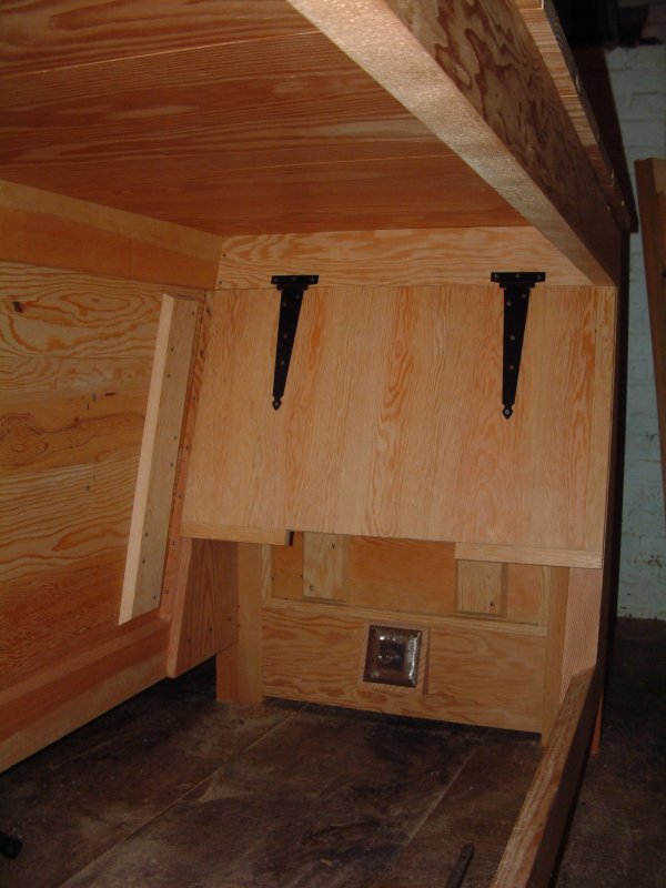
Again this end will be inaccessible as it will be very close to the side of the mill.
The bronze bearing for the top end of the bolting drum can be seen together with the traditional feed shoe support. |
|
|
|

|
|
This view shows the lower bearing for the bolting drum and the hinged door to access the cloth.
The hinged door is yet to be shaped to clear the rotating bolting drum. |
|
|
|
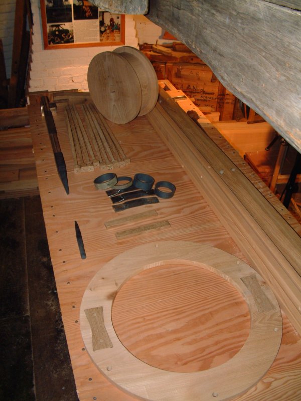
A selection of parts for the bolting drum and drive.
The oak shaft can be seen on the extreme right and the steel spindles on the left. The elm drive pulley is to the rear and the end ring is at the front. |
|
|
|
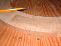
A close up of the oak dovetail pieces - these are dowelled in place and hold the end ring together without any glue!
The screws are temporary and will be replaced by forged nails when the bolter is assembled in the mill. |
|
|
back to top of page


. This is made from Douglas Fir and is fully mitred at the corners.")